TO VERIFY OHM’S LAW BY PLOTTING GRAPH BETWEEN CURRENT AND POTENTIAL DIFFERENCE
Ohm’s law
This law states that the current flowing through any conductor is directly proportional to the potential difference across it.
Theory
Let V be the potential difference between the points A and B and I be the current flowing through it. Then from Ohm’s law
V ∝ I
V = IR
Where, R is the resistance
Results
Least count of voltmeter = _________ Volt
Least count of Ammeter = _________ A
Table 1: Table for Current vs Potential difference
| Sl. No | Ammeter reading (A) | Voltmeter Reading (V) | Resistance (V/I) \Omega | Mean Resistance ( \Omega ) |
| 1 | ||||
| 2 | ||||
| 3 | ||||
| 4 | ||||
| 5 | ||||
| 6 | ||||
| 7 | ||||
| 8 | ||||
| 9 | ||||
| 10 |
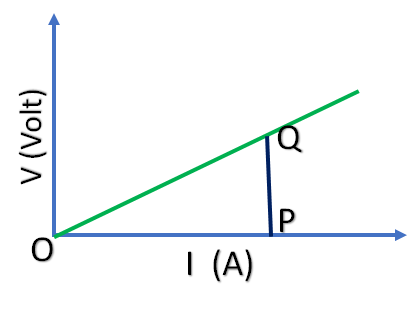
The value of resistance from graph is
R = PQ / OP = _________ \Omega
The obtained resistance from Table and graph are nearly equal.
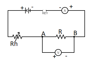
Precautions and Discussions
- The voltmeter should be connected in parallel and the ammeter in series with the circuit.
- The currents should enter the voltmeter and ammeter at the positive terminal and leave at the negative terminal.
- The key should not be entered for all the time. It should be inserted only when the measurements are taken to avoid the unnecessary heating of the wire.
- Zero error in measuring instruments should be eliminated.
Viva Voce questions with answers on verification of Ohm’s law experiment ( To verify Ohm’s law by plotting graph between current and potential difference)
1. State Ohm’s law
Answer: The voltage across a conductor is directly proportional to the current flowing through it, provided temperature and other physical conditions remain constant.
2. What is electric current?
Answer: The rate of flow of electric charges.
The unit of electric current is Ampere (A).
3. Define one ohm.
Answer: We know Resistance, R = V/I
1\Omega = \frac{1 volt}{1 A}
So, one ohm resistance is the resistance when 1 ampere current flows through a conductor when 1 volt potential difference is applied to it.
4. What are the factors on which resistance depends?
Answer: Resistance depends on the length and area of cross-section of a conductor.
R = \rho\frac{l}{A}
5. What is resistivity?
Answer: R = \rho\frac{l}{A}
when, l = 1m and A = 1m2 , then R = \rho
So, resistivity is the resistance of a conductor of unit length and unit cross-sectional area.
6. What is the unit of resistivity?
Answer: R = \rho\frac{l}{A}
\rho = R\frac{A}{l}
\rho = \Omega \frac{m^{2}}{m}
\rho = \Omega .m
7. How resistance of a conductor depends on temperature?
Answer: The resistance of a conductor increases with increase in temperature.
8. How ammeter is connected in a circuit?
Answer: Ammeter is connected in series in a circuit.
9. What is the resistance of an ideal ammeter?
Answer: As Ammeter is connected in series, its resistance should be very small. For ideal ammeter, the resistance is Zero.
10. How voltmeter is connected in a circuit?
Answer: Voltmeter is connected in parallel in a circuit.
11. What is the resistance of an ideal voltmeter ?
Answer: Voltmeter is connected in parallel, its resistance should be very high. For ideal voltmeter, the resistance is infinity.
12. What is the shape of V vs I graph for a conductor?
Answer: The voltage vs current graph is linear (straight line).
13. How the resistance of a conductor can be found from V vs I graph?
Answer: Resistance can be found from the slope of V vs I graph.
.